Energy Metering with the Portenta C33
This application note describes how to implement a simple energy meter with the Portenta C33.
Introduction
This application note explores the implementation of a simple yet useful energy meter using the Arduino® Portenta C33 and a non-invasive current transformer. The proposed energy meter enables real-time measurement and monitoring of electrical current consumption, providing valuable and useful insights into energy usage patterns to the user.
Non-invasive current transformers offer several advantages, including electrical safety, easy installation, and the ability to measure current in existing electrical circuits without interrupting the flow of current. These characteristics make them well-suited for applications such as energy metering, power monitoring, and load management.
The Portenta C33 features a powerful microcontroller and onboard wireless connectivity, making it an ideal choice for energy monitoring applications. The Portenta C33's onboard Wi-Fi® module enables seamless integration with wireless networks and facilitates communication with the Arduino Cloud platform.
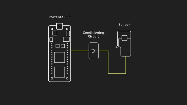
By combining the Portenta C33 and the SCT013-000 current transformer, you can quickly build an energy meter that can measure Root Means Square (RMS) current, power consumption, and communicates the data to the Arduino Cloud platform for further analysis and visualization.
Goals
The main goals of this application note are as follows:
- Develop a functional energy meter that can provide real-time insights into energy usage patterns, allowing users to track and analyze their energy consumption.
- Showcase the integration of the Portenta C33 board with a non-invasive current transformer to measure AC current.
- Calculate the RMS (Root Mean Square) value of a current waveform, providing an accurate representation of the actual current flowing through the circuit.
- Use the measured RMS current and a known AC voltage to calculate power consumption in Watts.
- Establish a connection between the Portenta C33 and the Arduino Cloud to send the measured RMS current data for further analysis, visualization, and remote monitoring.
Hardware and Software Requirements
Hardware Requirements
- Portenta C33 (x1)
- USB-C® cable (x1)
- Wi-Fi® W.FL antenna (x1)
- SCT013-000 current transformer (x1)
- Conditioner circuit (x1)
Software Requirements
- Arduino IDE 1.8.10+, Arduino IDE 2.0+, or Arduino Web Editor
- For the Wi-Fi® connectivity feature of Portenta C33, we will use Arduino Cloud. In case you do not have an account, create one for free here.
- The energy meter example sketch
Hardware Setup Overview
The electrical connections of the intended application design are shown in the diagram below:
The overview illustrates the connection from the sensor passing through a conditioner circuit and interfacing with the Portenta C33.
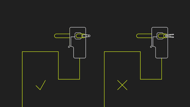
Take into account that only one AC wire must pass in between the current transformer, as shown below:
Measuring Current Using Non-Invasive Current Transformers
Non-invasive current transformers, such as the SCT013-000 current transformer used in this application note, provide a safe and convenient method for measuring electrical current, without the need for direct electrical connections. These transformers work on the principle of electromagnetic induction and consist of a primary winding and a secondary winding.
As shown in the animation below, the primary winding typically consists of a single turn or a few turns of a conductor, while the secondary winding consists of a large number of turns wound around a magnetic core. When an alternating current flows through the primary winding, it induces a proportional current in the secondary winding. This induced current can be measured and used to determine the magnitude of the primary current.
As shown in the animation below, the primary winding is typically a single turn or a few turns of a conductor, while the secondary winding is a large number of turns wound around a magnetic core. When an alternating current flows through the primary winding, it induces a proportional current in the secondary winding. This induced current can be measured and used to determine the magnitude of the primary current.
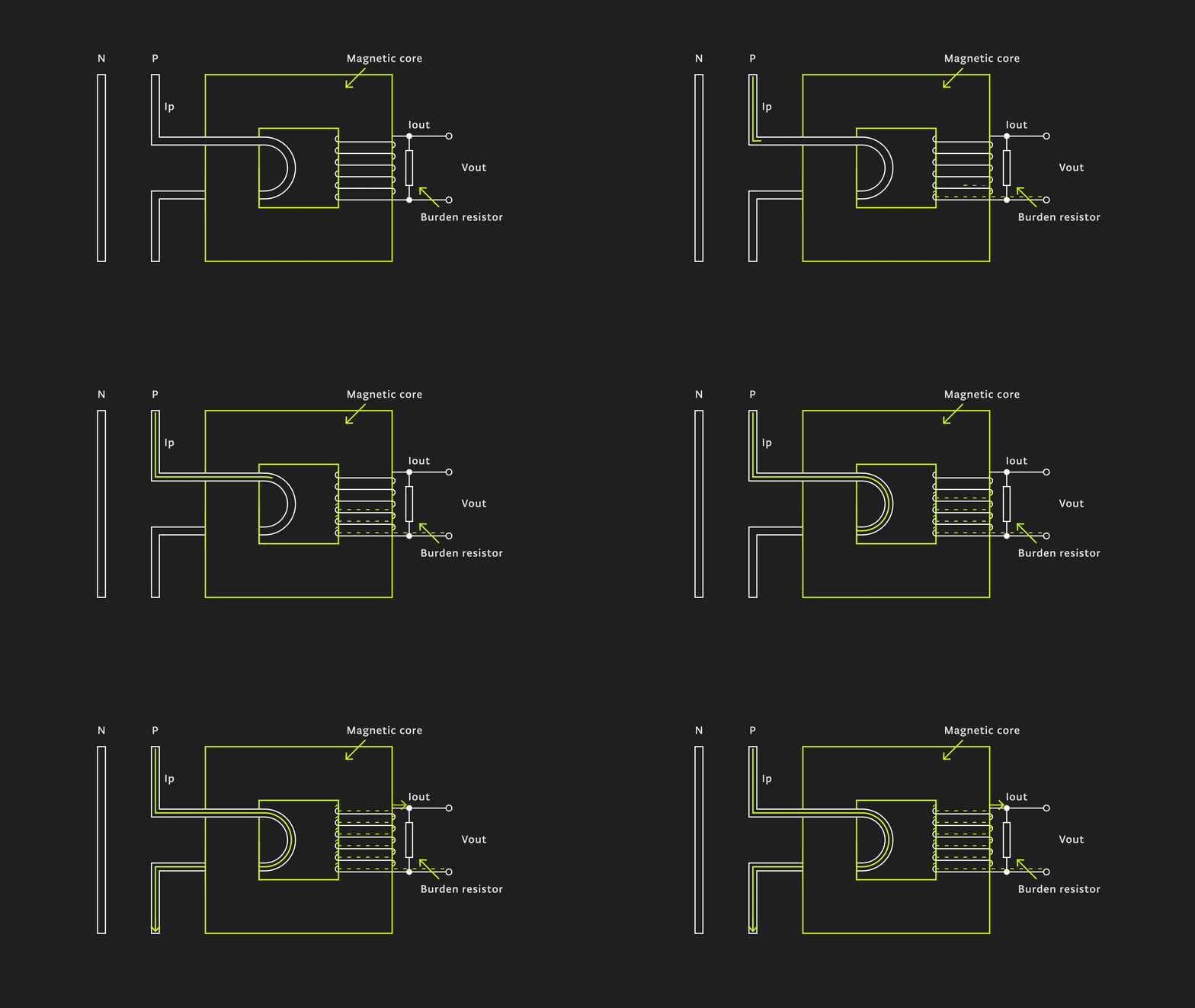
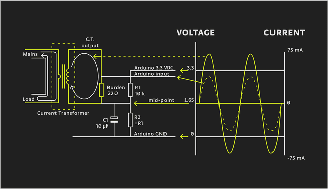
To accurately measure the induced current, a burden resistor is connected in parallel with the secondary winding of the current transformer. The burden resistor creates a voltage drop proportional to the secondary current, which can be measured using an analog or digital sensor, for example, the analog input pins of the Portenta C33. In this application note, the measured secondary current is converted into an RMS current value using appropriate calibration ratios and calculations.
The value of the burden resistor must be carefully chosen to match the physical characteristics of your current transformer and measurement sensor.
To calculate the ideal burden resistor some math is required. Below you can find the calculations done for the SCT013-000 current transformer used this the application note:
- Primary winding peak current (IP):

- Secondary winding peak current (IS):

- Ideal burden resistor (RBurden):

For this application note and the used non-invasive current transformer, the ideal burden resistor RBurden is 21.9 Ω; you can use a commercially available resistor value, for example, 22 Ω.
Non-invasive current transformers offer several advantages, including electrical safety, easy installation, and the ability to measure current in existing electrical circuits without interrupting the current flow. These characteristics make them well-suited for applications such as:
- Energy metering
- Power monitoring
- Load management
Non-Invasive Current Transformer Example Sketch
The non-invasive current transformer sketch has a simple structure which is explained below.
1/**2 Energy metering application note3 Name: current_cloud.ino4 Purpose: This sketch interfaces the Portenta C33 with the SCT013-000 current transformer 5 to measure RMS current and power.6
7 @author Arduino Team8 @version 1.0 20/06/239*/10
11// Import the properties and definitions for the Arduino Cloud integration12#include "thingProperties.h"13
14// Define a floating-point conversion factor for the SCT013-000 current transformer configuration15float Sensor_Factor = 51.8;16
17// Define floating-point variables for the Root Mean Square (RMS) current and apparent Power18float Irms, AP;19
20// Define an integer for the specific voltage of the geographical region21int Region_Voltage = 110;22
23// Define a boolean variable to control whether or not the sampling process is active24bool Sample_Switch = true;25
26// Define the pin where the current transformer is connected27#define TRANSFORMER_PIN A0 28
29void setup() {30 // Initialize the serial communication with a baud rate of 11520031 Serial.begin(115200);32
33 // Set the current transformer pin as input34 // Set the resolution of the analog read to 12 bits35 // Pause the execution of the program for one second36 pinMode(TRANSFORMER_PIN, INPUT);37 analogReadResolution(12);38 delay(1000); 39
40 // Call the function to setup the Arduino Cloud41 iot_cloud_setup();42}43
44void loop() {45 // Update the status of the Arduino Cloud46 ArduinoCloud.update();47 48 // If the sampling switch is active, calculate the RMS current49 if (Sample_Switch == true) {50 Irms = getCurrent(); 51
52 // Calculate apparent power53 AP = Irms * Region_Voltage; 54 55 // Print RMS current and apparent power to the IDE's Serial Monitor56 Serial.print(F("- I_rms [A]: "));57 Serial.print(Irms);58 Serial.print(F("- Apparent Power [VA]: "));59 Serial.print(AP);60 } else {61 // If the sampling switch is not active, print a message saying the energy measurement has been paused62 Serial.println(F("- Energy measurement has been paused!"));63 }64 65 // Update the RMS current and apparent power in the Arduino Cloud66 cloud_Current = Irms;67 cloud_ApparentPower = AP;68 69 // Pause the execution of the program for one second70 delay(1000); 71}72
73/**74 This function is executed every time a new value is received from the Arduino Cloud75 76 @param none77 @return none78*/79void onCloudCurrentChange() {80 // Print a debug message81 Serial.print(F("- Updated I_RMS value for IoT Cloud"));82}83
84/**85 Reads the designated analog pin, connected to a SCT013-000 current transformer and calculates RMS Current86 87 @param none88 @return RMS current (amperes)89*/90float getCurrent() {91 float Current = 0;92 float I_Sum = 0;93 int N = 0;94 long time = millis();95 96 // Collect samples for 0.5 seconds (approx. 30 cycles at 60 Hz)97 while(millis() - time < 500) { 98 99 // Read the analog pin100 int sensorValue = analogRead(TRANSFORMER_PIN);101 102 // Convert the analog reading to voltage103 float sensorVoltage = sensorValue * (3.1 / 4096.0);104
105 // Convert the sensor voltage to current106 Current = sensorVoltage * Sensor_Factor;107 108 // Calculate the sum of the squares of the current109 I_Sum += sq(Current); 110 N++;111 delay(1);112 }113
114 // Compensate for the negative semi-cycle quadratics115 I_Sum = I_Sum * 2; 116 117 // Calculate RMS current (average)118 Current = sqrt((I_Sum)/N); 119 return(Current);120}121
122/**123 Sets up the connection to the Arduino Cloud124 125 @param none126 @return none127*/128void iot_cloud_setup() {129 // Defined in thingProperties.h130 initProperties();131
132 // Connect to Arduino Cloud133 ArduinoCloud.begin(ArduinoIoTPreferredConnection);134 135 /*136 The following function allows you to obtain more information137 related to the state of network and IoT Cloud connection and errors138 the higher number the more granular information you’ll get.139 The default is 0 (only errors).140 Maximum is 4141 */142 setDebugMessageLevel(2);143 ArduinoCloud.printDebugInfo();144 145 sct_ratio = Sensor_Factor;146 system_Voltage = Region_Voltage;147 sample_Control = Sample_Switch;148}149
150/**151 This function is executed every time a new value from sct_ratio is received from the Arduino Cloud152 153 @param none154 @return none155*/156void onSctRatioChange() {157 Sensor_Factor = sct_ratio;158}159
160/*161 This function is executed every time a new value from system_Voltage is received from the Arduino Cloud162*/163void onSystemVoltageChange() {164 Region_Voltage = system_Voltage;165}166
167*168 This function is executed every time a new value from sample_Control is received from the Arduino Cloud169*/170void onSampleControlChange() {171 Sample_Switch = sample_Control;172 173 if (Sample_Switch == true){174 Serial.println(F("Energy measurement started - Arduino Cloud triggered"));175 }176 if (Sample_Switch == false){177 Serial.println(F("Eenrgy measurement paused - Arduino Cloud triggered"));178 }179}The following sections will help you to understand the main parts of the code.
Variables and Constants
The key variables and constants used in the sketch are:
1// Conversion factor for the specific sensor configuration2float Sensor_Factor = 51.8;3
4// RMS Current and Apparent Power variable5float Irms, AP;6
7// Voltage specific to the geographical region in volts8int Region_Voltage = 110;9
10// Boolean variable to control measurement sampling11bool Sample_Switch = true;12
13// Analog pin to which the current transformer is connected14#define TRANSFORMER_PIN A0
: A conversion factor used to convert the raw current transformer reading to an RMS current value.Sensor_Factor
andIrms
: Variables used to store the RMS current and apparent power respectively.AP
: The voltage of the power system you are monitoring. This varies depending on the country and the type of power system.Region_Voltage
: A boolean switch to control whether or not your Portenta C33 should be measuring power. If it is true, your Portenta C33 will measure power.Sample_Switch
: The pin on your Portenta C33 board that the current transformer is connected to.TRANSFORMER_PIN
Initialization Function
The
setup()1void setup() {2 // Initialize the serial communication with a baud rate of 1152003 Serial.begin(115200);4
5 // Set the current transformer pin as input6 // Set the resolution of the analog read to 12 bits7 // Pause the execution of the program for one second8 pinMode(TRANSFORMER_PIN, INPUT);9 analogReadResolution(12);10 delay(1000); 11
12 // Call the function to setup the Arduino Cloud13 iot_cloud_setup();14}This function runs once when the Portenta C33 starts:
- It initializes the serial communication.
- Sets the pin mode of the current transformer input pin to input.
- Sets the ADC resolution to 12 bits and waits for a second for the system to stabilize.
- Finally calls the
function to set up the Arduino Cloud connection.iot_cloud_setup()
The Main Loop
The main loop of the sketch is as follows:
1void loop() {2 // Update the status of the Arduino Cloud3 ArduinoCloud.update();4 5 // If the sampling switch is active, calculate the RMS current6 if (Sample_Switch == true) {7 Irms = getCurrent(); 8
9 // Calculate apparent power10 AP = Irms * Region_Voltage; 11 12 // Print RMS current and apparent power to the IDE's Serial Monitor13 Serial.print(F("- I_RMS [A]: "));14 Serial.print(Irms);15 Serial.print(F("- Apparent power [VA]: "));16 Serial.print(AP);17 } else {18 // If the sampling switch is not active, print a message saying the energy measurement has been paused19 Serial.println(F("- Energy measurement has been paused!"));20 }21 22 // Update the RMS current and apparent power in the Arduino Cloud23 cloud_Current = Irms;24 cloud_ApparentPower = AP;25 26 // Pause the execution of the program for one second27 delay(1000); 28}The main
loop()- It first updates the Arduino Cloud connection.
- If the
is true, it measures current, calculates apparent power, and prints them to the IDE's Serial Monitor.Sample_Switch - If
is false, it simply prints that the energy measurement is paused.Sample_Switch - It then updates the
andcloud_Current
variables with the local values of current and apparent power, then waits for a second before the next iteration.cloud_ApparentPower
User Functions
The
iot_cloud_setup()1void iot_cloud_setup() {2 // Defined in thingProperties.h3 initProperties();4
5 // Connect to Arduino Cloud6 ArduinoCloud.begin(ArduinoIoTPreferredConnection);7 8 /*9 The following function allows you to obtain more information10 related to the state of network and IoT Cloud connection and errors11 the higher number the more granular information you’ll get.12 The default is 0 (only errors).13 Maximum is 414 */15 setDebugMessageLevel(2);16 ArduinoCloud.printDebugInfo();17 18 sct_ratio = Sensor_Factor;19 system_Voltage = Region_Voltage;20 sample_Control = Sample_Switch;21}This function is responsible for setting up the connection with the Arduino Cloud:
- It initiates the properties of the Cloud connection.
- Begins the Cloud connection with the preferred connection method.
- Sets the debug message level to 2 for detailed debugging, and prints the debug information.
The variables
sct_ratiosystem_Voltagesample_ControlNow, let's talk about the
getCurrent()1float getCurrent() {2 float Current = 0;3 float I_Sum = 0;4 int N = 0;5 long time = millis();6 7 // Collect samples for 0.5 seconds (approx. 30 cycles at 60 Hz)8 while(millis() - time < 500) { 9 10 // Read the analog pin11 int sensorValue = analogRead(TRANSFORMER_PIN);12 13 // Convert the analog reading to voltage14 float sensorVoltage = sensorValue * (3.1 / 4096.0);15
16 // Convert the sensor voltage to current17 Current = sensorVoltage * Sensor_Factor;18 19 // Calculate the sum of the squares of the current20 I_Sum += sq(Current); 21 N++;22 delay(1);23 }24
25 // Compensate for the negative semi-cycle quadratics26 I_Sum = I_Sum * 2; 27 28 // Calculate RMS current (average)29 Current = sqrt((I_Sum)/N); 30 return(Current);31}The
getCurrent()Finally,
onSctRatioChange()onSystemVoltageChange()onSampleControlChange()onSctRatioChange()Sensor_FactorFull Example Code
The complete example code can be downloaded here. The
thingProperties.hArduino Cloud Dashboard
The Arduino Cloud allows to create a dashboard with professional real-time Human-Computer Interaction (HCI) as can be seen in the following animation, showing an active Portenta C33 board:
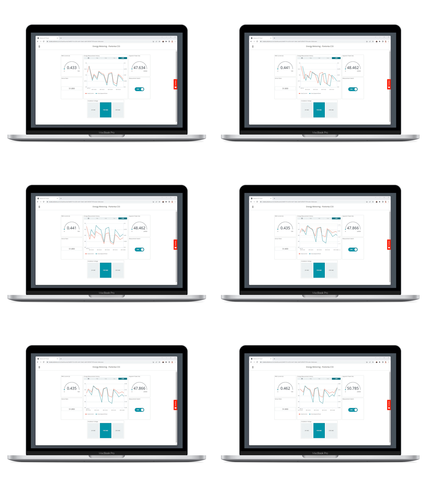
One of the standout features of the Arduino Cloud Dashboard is the ability to update the current transformer's ratio in real time. This feature becomes particularly useful when you need to switch to a different current transformer in a live deployment scenario. Different current transformers can possess different electrical characteristics more or less convenient for different scenarios, and the real-time update capability simplifies the swap between them.
Additionally, the dashboard lets you select the installation voltage to meet the requirements of your site. This adaptability underscores the flexibility and user-friendliness of the Arduino Cloud Dashboard, making it an invaluable tool for handling real-time sensor data.
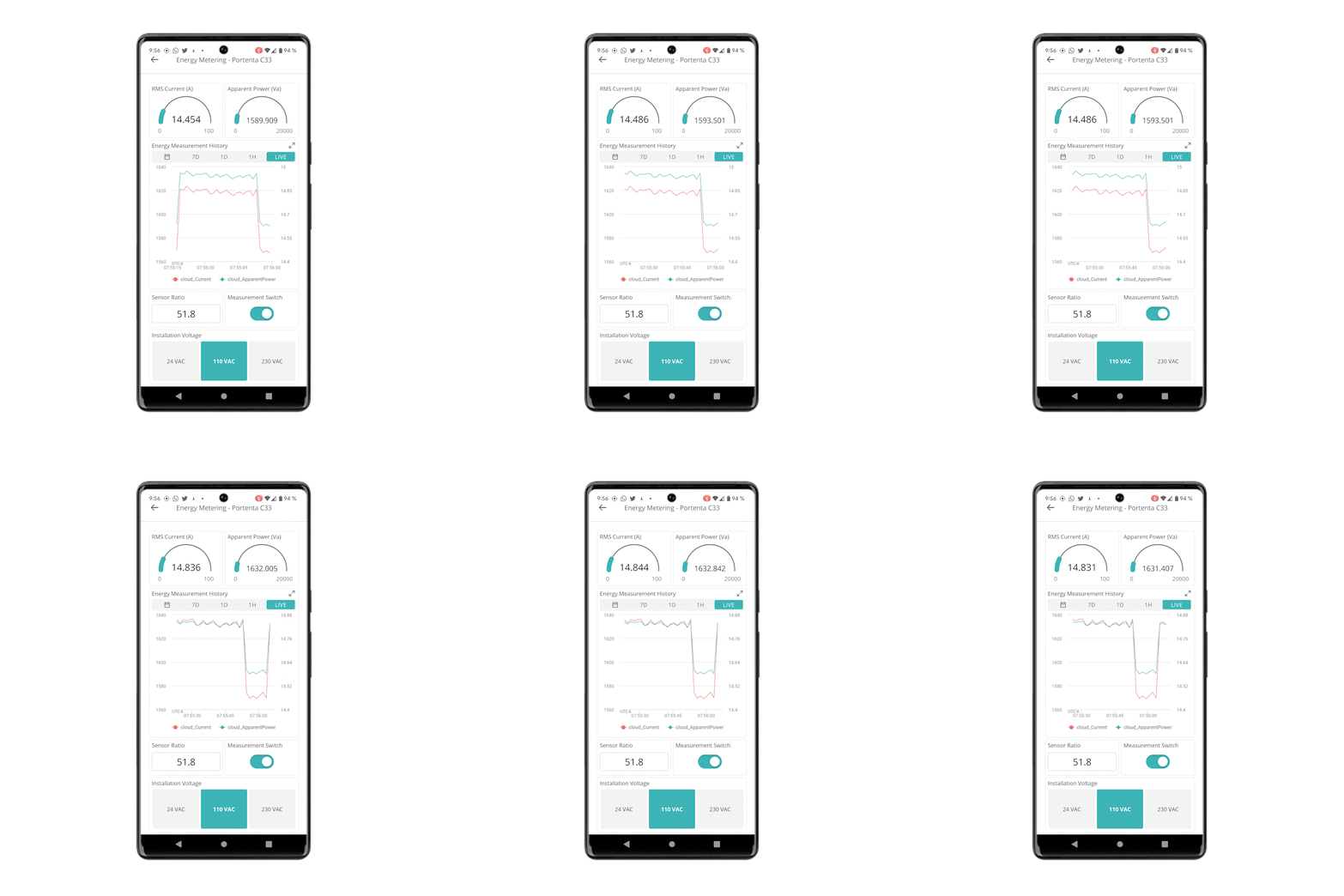
On a mobile phone, the Arduino Cloud dashboard displays the information as the previous figure. It provides the complete interface you would use on a desktop platform, making it a very useful feature to access the dashboard wherever you are.
Conclusions
In this application note, we delved into the interaction between a Portenta C33 board and the SCT013-000 current transformer. We examined how the Arduino Cloud enables us to visualize and analyze real-time and historical sensor data intuitively.
By using the Portenta C33 board and the Arduino Cloud, you can transform raw sensor data into meaningful insights. Whether it is reading the RMS current and apparent power information, altering the current transformer configurations in real-time, or adapting to unique site requirements, this application note offers a robust and versatile system for handling these tasks.
One of the key takeaways from this application note is its potential for this application in various real-world scenarios. By integrating IoT and Cloud capabilities, we can effectively monitor and manage energy usage, leading to more efficient power consumption and contributing to a sustainable future.
Next Steps
Now that you have learned to deploy a Portenta C33 with SCT013-000 current transformer, using the on-demand remote actuation and real-time data visualization of the Arduino Cloud platform, you will be able to expand the application further by adding new measurement equipment with similar characteristics. You could also deploy multiple sensors connected to different boards, creating a cluster to gather energy measurements from every point of interest in an electrical installation.
Suggest changes
The content on docs.arduino.cc is facilitated through a public GitHub repository. If you see anything wrong, you can edit this page here.
License
The Arduino documentation is licensed under the Creative Commons Attribution-Share Alike 4.0 license.