Modbus TCP with Portenta Machine Control & Opta™
Learn to use Modbus TCP communication on a real industrial application using a Portenta Machine Control, Opta™, a temperature sensor, and the Arduino® PLC IDE.
Overview & Video Tutorial
In this tutorial, a Portenta Machine Control and an Opta™ micro PLC will be used as server and client respectively to share temperature information through Modbus TCP using the PLC IDE. The server will do the measurements using a type K thermocouple and the client will activate its relay outputs when a certain threshold is reached.
We have prepared a detailed guide in video format in case you are a visual learner.
If you prefer to follow the tutorial in a written format, or need to review the steps and code done in the video tutorial, in the following sections you will find a step-by-step guide explaining how the temperature measurement and Modbus communication between both devices were done.
Goals
- Learn how to measure temperature with the Portenta Machine Control using a thermocouple and the PLC IDE
- Discover how to use the Modbus protocol over TCP/IP using the PLC IDE
- Leverage Arduino Pro products for real industrial applications
Hardware and Software Requirements
Hardware
- Portenta Machine Control (x1)
- Opta™ (x1)
- Type K thermocouple (x1)
- Ethernet cables (x2)
- Wired internet access
- 24 VDC/0.5 A power supply (x2)
Software
Instructions
Solution Wiring
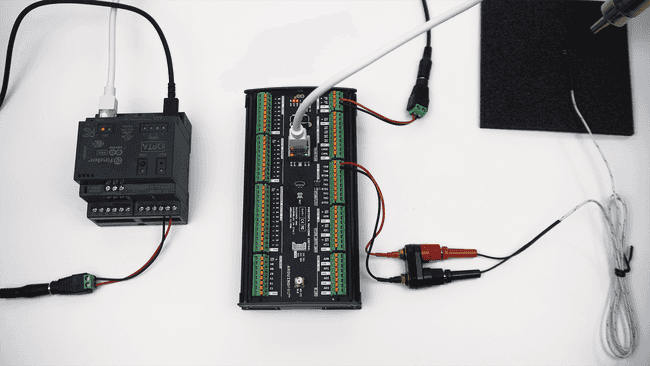
In the Portenta Machine Control: connect the thermocouple terminals to TP0 and TN0 respectively and the 24 VDC power supply to the 24-volt input and GND.
In the Opta™ micro PLC: connect the power supply to the respective inputs on the screw terminals.
Connect both the Portenta Machine Control and the Opta™ to your local network using ethernet cables.
Portenta Machine Control Setup
After downloading the PLC IDE, open it and create a new project for the Portenta Machine Control.
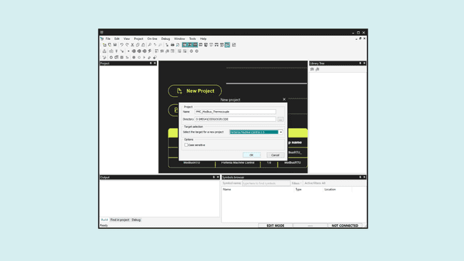
A license is needed for this product to be used with the PLC IDE, you can buy it directly from the Arduino store, and it will include the product key to activate the device.
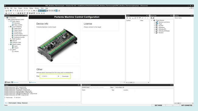
Connect the Machine Control to the computer using a micro USB cable, the board needs to run a specific program (runtime) in order to interact with the PLC IDE. To flash it, select the device serial port and click on download.
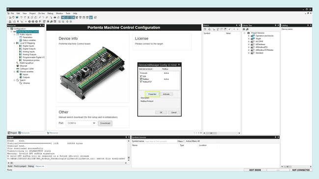
Once the runtime is flashed, navigate to On-line > Set up communication, open the Modbus properties and select the secondary serial port, then click "OK".
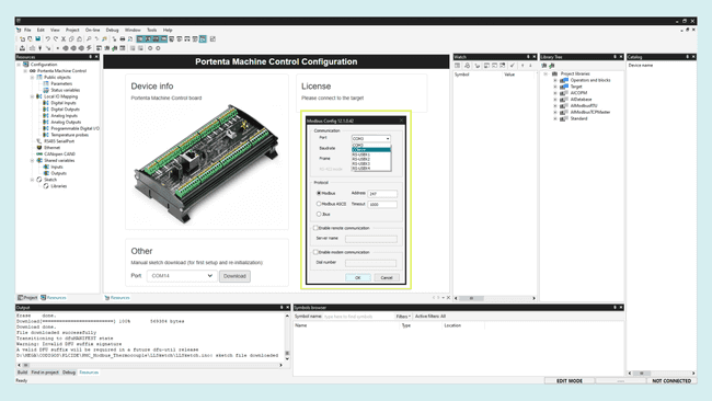
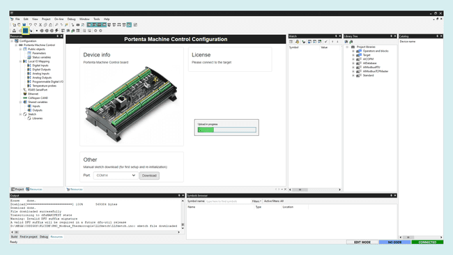
Now, in the upper left corner, click on the Connect button and wait for the base program to be uploaded. A green Connected flag should appear in the lower right corner if everything goes well.
The device will show its activation status, in this case, No License as it is the first time using it with the PLC IDE. To activate it, paste the product key you bought in the highlighted box and click on Activate.
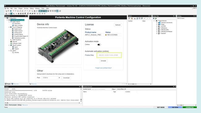
After the activation, the status should say OK. Now you are ready to start programming the Portenta Machine Control with the PLC IDE.
To learn more about the PLC IDE first setup, continue reading this detailed guide.
Modbus TCP - Server
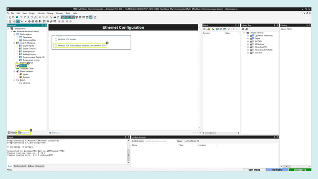
For the Modbus TCP configuration, on the resources tab go to the Ethernet section. As noticed, the Modbus TCP Slave mode is always enabled, so you don't have to make any changes.
Go to the sketch editor and uncomment the library and setup function code lines. As the IP, we must use the same as the Portenta Machine Control, as it is connected to your local network, you can find it on its configurations.
In this case, the following configurations are used:
1// Enable usage of EtherClass, to set static IP address and other2#include <PortentaEthernet.h>3arduino::EthernetClass eth(&m_netInterface);4
5void setup()6{7 // Configure static IP address8 IPAddress ip(10, 0, 0, 157); // Portenta Machine Control IP address9 IPAddress dns(10, 0, 0, 1); // gateway IP address10 IPAddress gateway(10, 0, 0, 1); // gateway IP address11 IPAddress subnet(255, 255, 255, 0); 12 // If cable is not connected this will block the start of PLC with about 60s of timeout!13 eth.begin(ip, dns, gateway, subnet);14
15}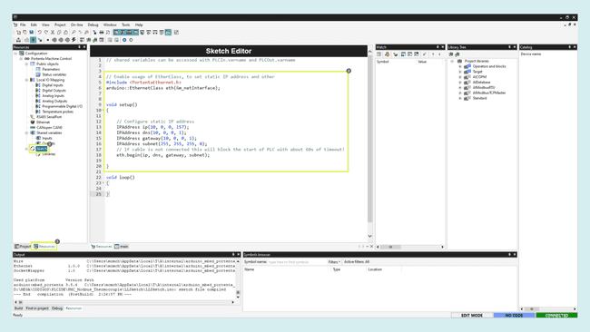
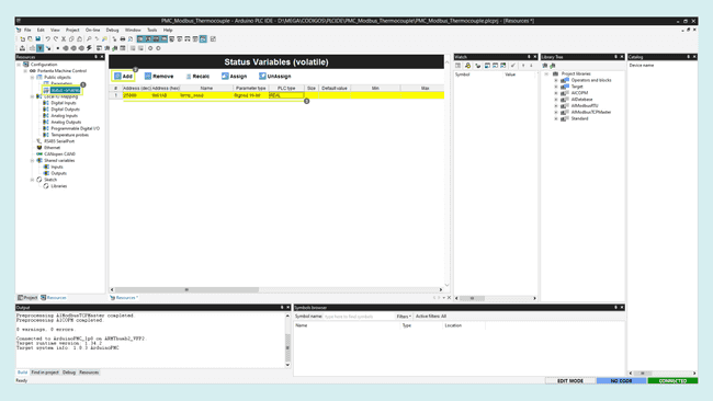
Now create the variable that will be shared with the temperature sensor data in the network. Go to status variables and click on Add. Configure it as follows:
- Name:
temp_send - Address:
25000 - PLC type:
REAL
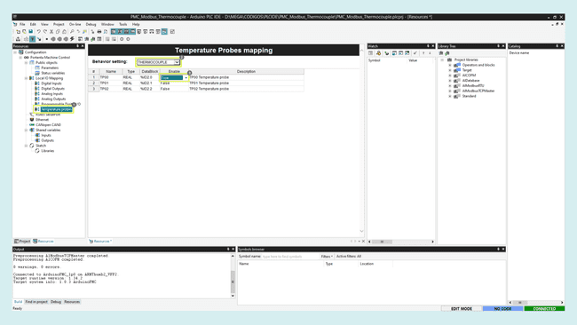
Next go to Temperature probes and select the sensor type, for this tutorial, enable the thermocouple connected to the first channel by setting it to true.
Finally, go to the main program in project and match the temperature variable with the temperature sensor lectures as follows:
1temp_send := sysTempProbes[0].temperature;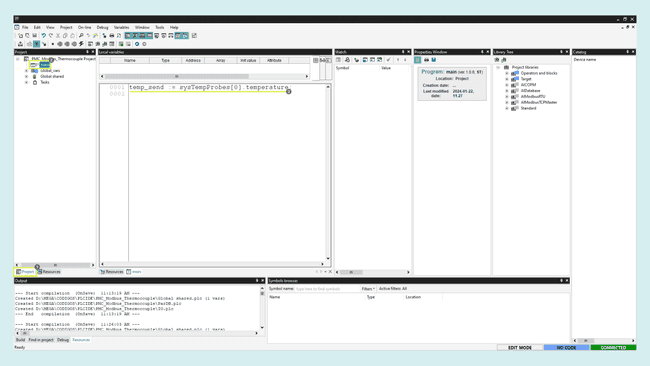
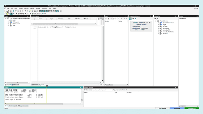
To check if everything is okay, click on compile, and if no error is shown, you can upload the code to your Portenta Machine Control.
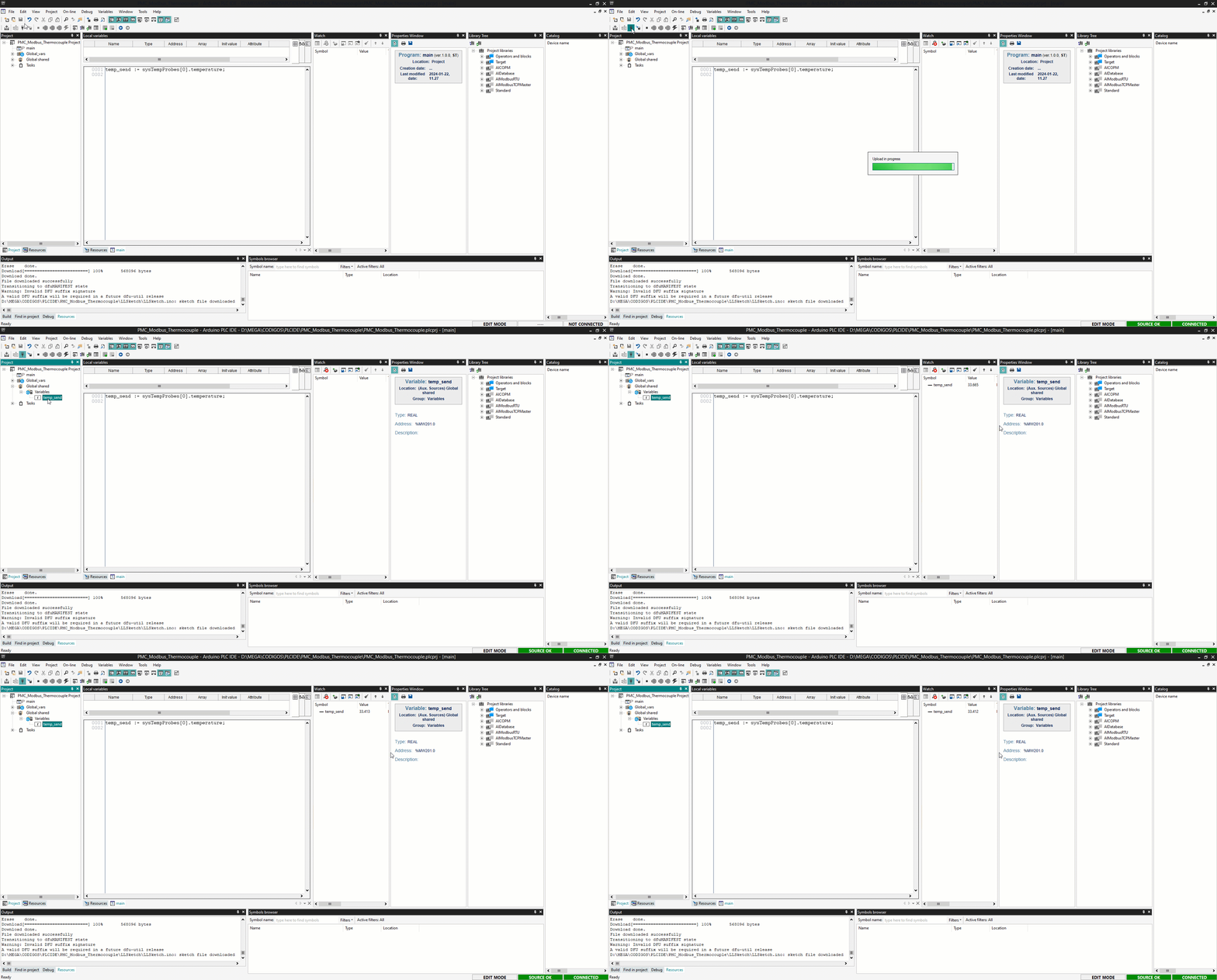
Once uploaded, click on the Connect button again. Now you can monitor the temp_send variable in the Watch window dragging and dropping it from the Global shared variables in the project tab.
You should see the temperature value measured by the sensor inside the "Watch" window.
Opta™ Micro PLC Setup
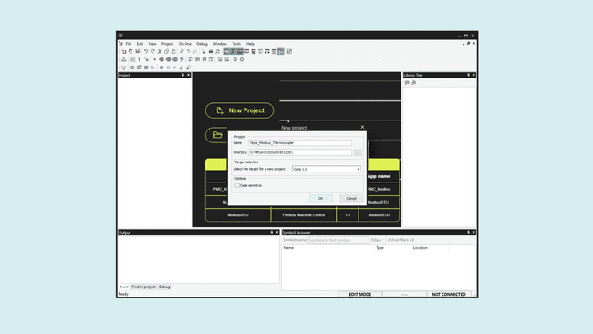
Now the server is configured, create a new project, this time for the Opta™ micro PLC that will be the Client or Master.
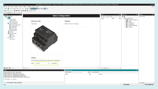
Upload the runtime for Opta™ by selecting its serial port and clicking on the Download button as before.
Once the runtime is flashed, with your Opta™ connected to your router, search for its IP address on the router configurations.
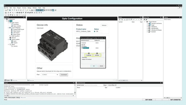
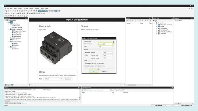
On the PLC IDE, navigate to On-line > Set up communication, activate and then open the ModbusTCP properties. Add the Opta™ IP address, then click "OK".
Now, in the upper left corner, click on the Connect button and wait for the base program to be uploaded. A green Connected flag should appear in the lower right corner if everything goes well.
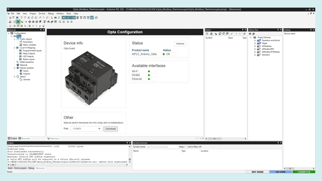
The Opta™ is Pre-Licensed so you don't have to buy any license to use it with the PLC IDE
If the Opta status says No License, click on the Activate PLC runtime button to activate it. Learn more about this case in this guide.
Modbus TCP - Client
With the Opta™ successfully connected to the PLC IDE, it is time to configure the Modbus TCP communication.
In the Ethernet tab, enable the Modbus TCP Master mode.
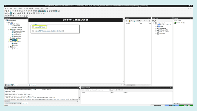
Then right-click on the Ethernet tab, click on Add and select the Generic Modbus device.
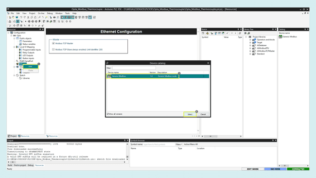
On the
Generic Modbus_1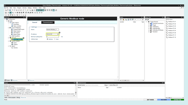
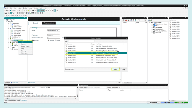
Right-click on the device and add the FC-04 Modbus function that will let us read the server input registers.
Now click on the function and in the general settings, enter the shared variable address that you defined earlier in the server,
25000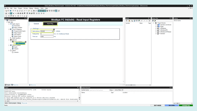
In the Input Register tab, create a label for it, which could be
temp_reg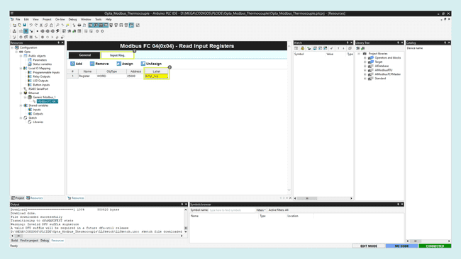
Go to the sketch editor and uncomment the library and setup function code lines. As the IP, we must use the same as the Opta™.
In this case the following configurations are used:
1// Enable usage of EtherClass, to set static IP address and other2#include <PortentaEthernet.h>3arduino::EthernetClass eth(&m_netInterface);4
5void setup()6{7 // Configure static IP address8 IPAddress ip(10, 0, 0, 227); // Opta IP address9 IPAddress dns(10, 0, 0, 1); // gateway IP address10 IPAddress gateway(10, 0, 0, 1); // gateway IP address11 IPAddress subnet(255, 255, 255, 0); 12 // If cable is not connected this will block the start of PLC with about 60s of timeout!13 eth.begin(ip, dns, gateway, subnet);14
15}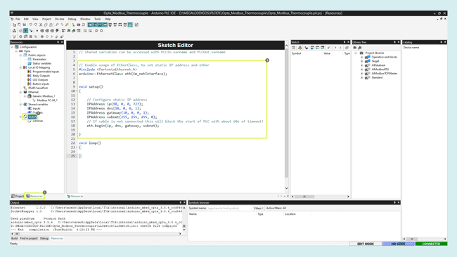
Finally, define the Opta™ outputs behavior in function of the temperature read from the Portenta Machine Control. To do this, go to the resources tab > Relay Outputs and give a variable name to each relay, in this case, call them
relay_1relay_2relay_3relay_4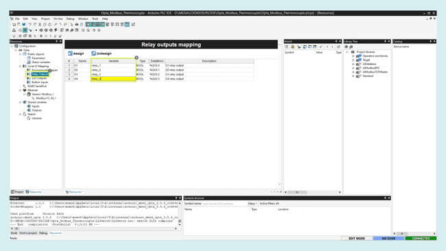
The same with the LED outputs,
LED1LED2LED3LED4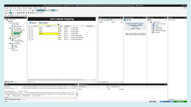
Now go to the main code in the Project tab. Create a variable by right-clicking on the local variables window and then insert, call it temp_local and integer as the type.
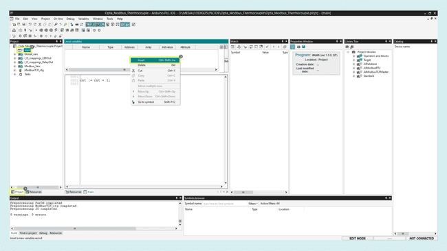
In the code editor, match the local variable with the shared one sent by the Portenta Machine Control.
Once stored locally, design the logic to control the outputs as you want. In this case, four different temperature levels will be set to control each output with the temperature rise respectively. Copy and paste the following script into the main code section.
1temp_local:= temp_reg;2
3IF temp_local >= 30 THEN4 relay_1 := TRUE;5 LED1 := TRUE; 6ELSE7 relay_1 := FALSE;8 LED1 := FALSE;9END_IF;10
11IF temp_local >= 50 THEN 12 relay_2 := TRUE;13 LED2 := TRUE;14ELSE15 relay_2 := FALSE;16 LED2 := FALSE;17END_IF;18
19IF temp_local >= 70 THEN 20 relay_3 := TRUE;21 LED3 := TRUE;22ELSE23 relay_3 := FALSE;24 LED3 := FALSE; 25END_IF;26
27IF temp_local >= 100 THEN 28 relay_4 := TRUE;29 LED4 := TRUE;30ELSE31 relay_4 := FALSE;32 LED4 := FALSE; 33END_IF;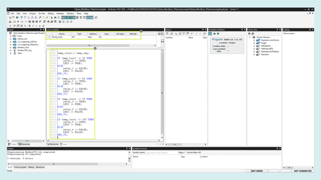
With the final code written, compile the project and upload it the the Opta™ micro PLC.
Final Test
You can leave each device connected separately to the internet router or connect them together directly with one ethernet cable. The first option will let you update the preferred device remotely as you can access it through the local network.
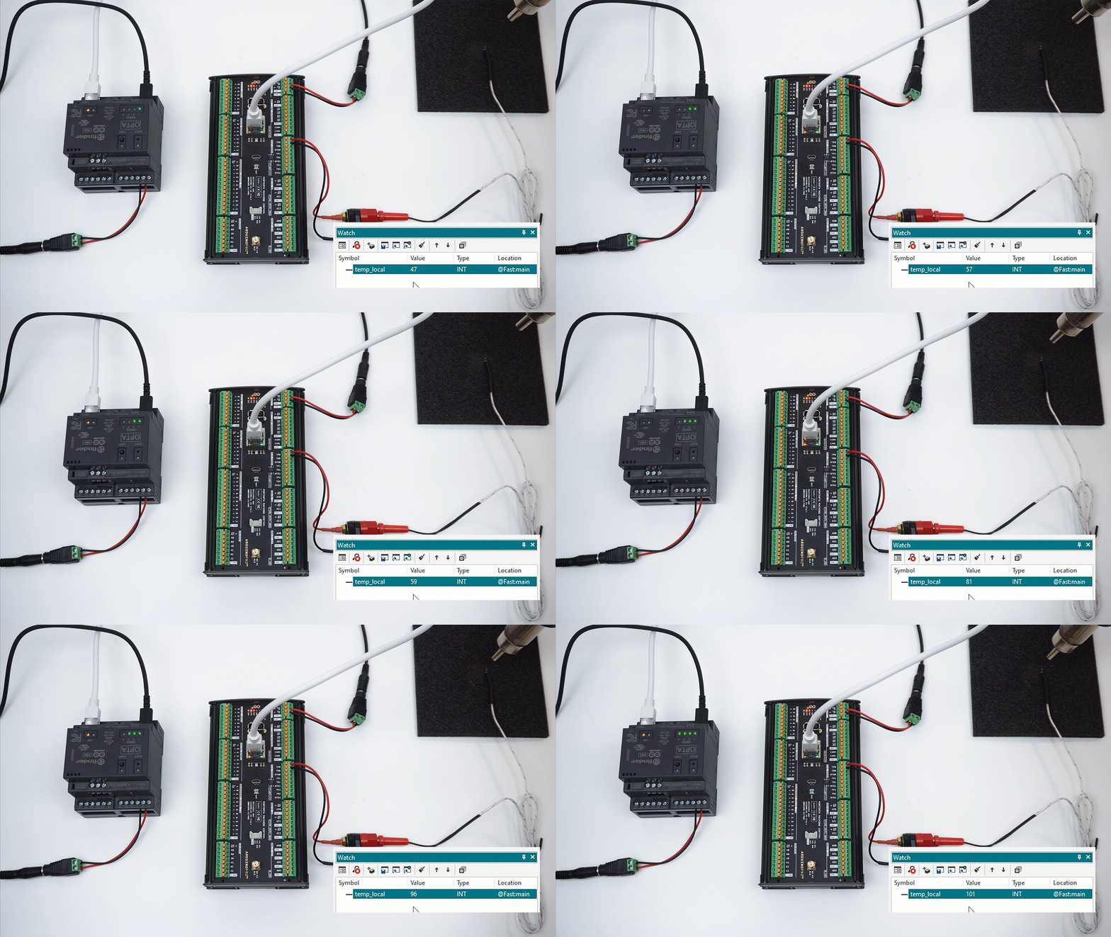
Now you can expose the temperature sensor to some heat and monitor it from the PLC IDE. The Opta™ relay outputs and LEDs will close and turn on when the temperature surpasses the programmed thresholds respectively.
Conclusion
In this tutorial you learned how to communicate two Arduino PRO products using the Modbus TCP protocol, demonstrating a simple application of sharing temperature data to control the outputs of the devices.
As you can notice, the configuration process is very straightforward and the results were as expected, being a good starting point to adapt the work done here to create your own professional solution.
Next Steps
Extend your knowledge about the Portenta Machine Control, PLC IDE and the variety of industrial protocols it supports by following these tutorials:
Suggest changes
The content on docs.arduino.cc is facilitated through a public GitHub repository. If you see anything wrong, you can edit this page here.
License
The Arduino documentation is licensed under the Creative Commons Attribution-Share Alike 4.0 license.