Arduino UNO R4 Minima OPAMP
Learn how to use the built-in Operational Amplifier in the UNO R4 Minima
In this tutorial, you will learn how to use the built-in operational amplifier (OPAMP) featured on the Arduino UNO R4 Minima. Operational amplifiers are very versatile and can be used to e.g. mirror an electrical signal or amplify it.
Goals
In this article, you will learn:
- about the OPAMP feature onboard the UNO R4 Minima,
- about the basics of the OPAMP library,
- how to mirror a voltage signal,
- how to amplify a voltage signal.
Hardware & Software Needed
To follow along with this article, you will need the following hardware:
- Arduino UNO R4 Minima
- resistors
- Jumper wires
Operational Amplifier (OPAMP)
An OPAMP is a versatile and widely used electronic component that belongs to the class of analog integrated circuits. Its primary function is to amplify voltage signals but they are very versatile and can be used to:
- mirror an input voltage to its output,
- amplify a small analog voltage to its output pin, the UNO R4's output voltage range is 0 to ~4.7 V,
- compare two input voltages and give a binary "higher" or "lower" output,
- integrate and differentiate signals.
Voltage Follower
The simplest way to test the OPAMP is to configure it as a voltage follower by connecting A2 to A3. In this setup, the voltage at A3 should mimic the voltage applied to A1. For instance, if you connect A1 to the ground (GND), the OPAMP output at A3 should also be at the ground potential. Similarly, if you connect A1 to 3.3 V, the output at A3 should be approximately 3.3 V.
Circuit
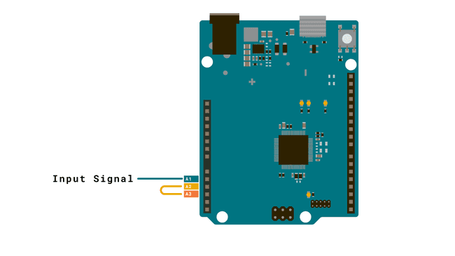
Voltage Amplifier
Caution: When amplifying the voltage of a battery using an operational amplifier, you should be aware of potential risks. The amplification process can lead to a high current draw, essentially placing a significant load on the battery, which may result in overheating, damage, or even pose a security risk. To mitigate this risk, you may for example add a resistor in series with the battery.
A voltage amplifier, as the name suggests, amplifies the voltage. A simple 2x amplifier can be built using e.g. two
10kGNDThe amplified output signal should not go above ~4.7 V, otherwise clipping will appear and you can damage the board
Below is a capture of an oscilloscope in which an approx. 2 V square wave (green, channel 2) is amplified to a 4 V square wave (yellow, channel 1) with the circuit shown below. The input signal was generated by a function generation (and shared GND was connected).
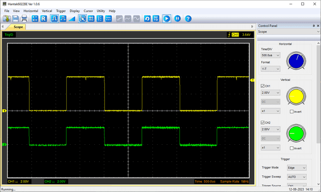
But let's say you want to amplify the voltage signal 4x instead of 2x. The amplification of an OPAMP mainly depends on the chosen resistor values. Take a look at the formula below:
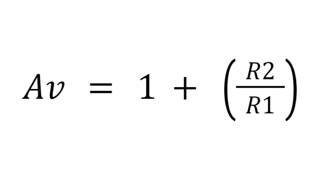
Av = Amplified Voltage (V)
R1 = Resistor connected to Ground (Ω)
R2 = Feedback resistor (Ω)
We know we want to amplify the voltage times four so:
Av = 4 V
Now, we need to figure out what resistors to choose. Because we only can solve for one unknown value we choose a predefined value for one of the resistors, e.g. 10k Ω for R1.
R1 = 10k Ω
Your formula should now look like this:
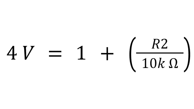
That leaves R2 as the only unknown variable. Now, Subtract one from both sides and multiply by ten, which leaves us with:
R2 = 30k Ω
Circuit
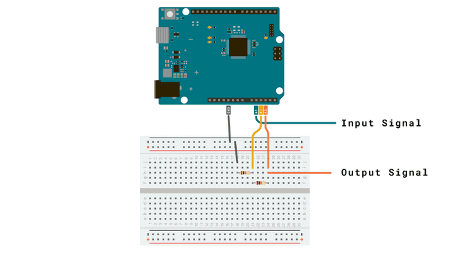
Read more about an amplifier circuit here.
Code
To start up the opamp, simply include the library and call
OPAMP.begin(speed)speedOPAMP_SPEED_LOWSPEEDOPAMP_SPEED_HIGHSPEED1#include <OPAMP.h>2
3void setup () {4 OPAMP.begin(OPAMP_SPEED_HIGHSPEED);5}6
7void loop() {}Suggest changes
The content on docs.arduino.cc is facilitated through a public GitHub repository. If you see anything wrong, you can edit this page here.
License
The Arduino documentation is licensed under the Creative Commons Attribution-Share Alike 4.0 license.